Belimo Actuator Wiring Diagram

Item s in download folder.
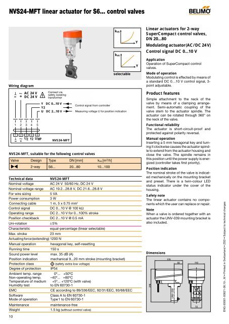
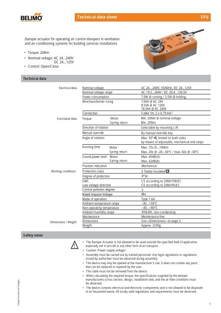
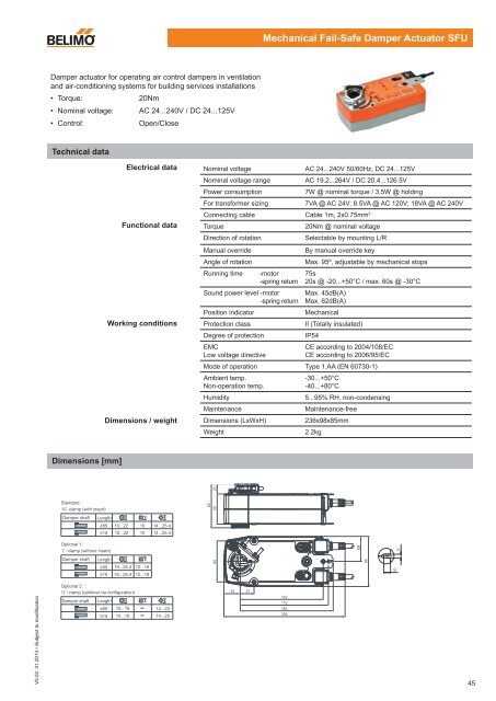
Belimo actuator wiring diagram. Negative leg of the control signal. A wiring diagram is a streamlined conventional pictorial depiction of an electrical circuit. Call belimo now 1 800 543 9038 available 8 30am to 8pm est. Leg of control.
Power consumption and input impedance must be observed. Collection of belimo tfb120 s wiring diagram. To find wiring diagrams for actuators and control valves follow the link for the wiring for damper actuators and control valves guide. Cable works well with belimo actuators.
Variety of belimo tfb120 s wiring diagram. Actuators may be connected in parallel. Wiring diagrams installation notes provide overload protection and disconnect as required. Actuators belimo damper actuators are designed for use in a wide variety of hvac applications ensuring performance reliability and lower power consumption.
Review job requirements and determine whether a plenum or appliance rated cable is appropriate. It reveals the elements of the circuit as streamlined shapes and the power and also signal connections between the gadgets. To learn how to use the belimo ps 100 power supply and signal generator to troubleshoot a belimo actuator watch the youtube video. Provide overload protection and disconnect as required.
Actuators hot wire must be connected to the control board common. Collection of belimo actuators wiring diagram. Only connect common to neg. Fire smoke actuators.
Items in your download folder download folder is empty. Actuators may also be powered by 24 vdc. A wiring diagram generally offers info regarding the family member placement as well as plan of devices and terminals on the gadgets to assist in building or servicing the gadget. It reveals the elements of the circuit as simplified forms as well as the power and also signal links in between the devices.
Actuators may also be powered by 24 vdc. A wiring diagram is a streamlined conventional photographic depiction of an electric circuit. With a comprehensive torque range 18 to 1400 in lbs suited for damper sizes as small as 6 inch round allowing the ability to direct mount on standard damper shafts or jackshafts. Leg of control circuits.
It shows the parts of the circuit as streamlined forms as well as the power and signal links in between the gadgets. A wiring diagram usually provides information regarding the relative position as well as plan of tools as well as terminals on the gadgets to help in structure or servicing the tool. Should i use a diode for floating control actuators. A wiring diagram is a streamlined traditional pictorial representation of an electrical circuit.
Actuators hot wire must be connected to the control board common. Only connect common to neg. Actuators shall be as manufactured by belimo. Actuators non fail safe actuators.


