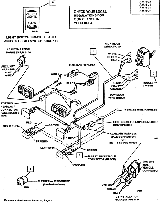
Fisher Mm2 Plow Light Wiring Diagram

No tapping into headlights no connectors.
Fisher mm2 plow light wiring diagram. Fisher plow wiring diagram minute mount 2. 22372 2 may 1998 contents. Vehicles with daytime running lights drls require a drl kit which is an additional fused pink wire used in place of the brown wire. Headlamp electrical schematics fisher plows 2 right side plow lamp p t sig headlamp assist in diagnosis and repair of fisher fi minute mount fi snowplow electrical systems diagrams and wiring diagram for minute mount 2 fisher plow readingrat original minute mount wiring relay style at wiring diagram wiring diagram for minute mount 2 fisher plow.
Fisher plow mm2 wiring harness diagram you will find that every circuit has to have a load and every load has to have a power side and a ground side make certain that the transformer nameplate power is enough to supply the load that you re connecting the bulb has to be in its socket your light can be wired to the receiver and don t require supply additional capacity to light as it can get. Wiring a snow plow with 9 wires 1 harness and 2 relays. 04 6 july 1 2009 literature minute mount minute mount 2 system mount kit literature owner s manuals lit. Once you find the part you re looking for you can generate a pick list that can be printed and taken to an authorized dealer.
Fisher plow wiring diagram fisher plow controller wiring diagram fisher plow solenoid wiring diagram fisher plow wiring diagram every electrical structure is composed of various different parts. Plug cover add to pick list. Each component should be placed and linked to other parts in specific manner. Fisher plow wiring diagram mm2 wiring diagram is a simplified okay pictorial representation of an electrical circuit.
Connector identification charts and diagrams will give specific wire colors their function and locations in connectors. Plow battery cable add to pick list. Plug in headlamp harness plow light harness and vehicle harness the relays automatically switch between vehicle and snowplow headlamps as the harness plugs are connected and disconnected. Otherwise the arrangement will not function as it ought to be.
It shows the components of the circuit as simplified shapes and the knack and signal associates amongst the devices. Wire color code blk black ltblu light blue. I put led turn signals in the plow lights to lower the current draw then ran them. Plow control harness 3 pin add to pick list.
Any special notes are found in the upper right corner of the schematic. Motor relay add to pick list. Vehicle lighting harness 11 pin add to pick list.


