Gamecube Controller Wiring Diagram Right Stick

Circuit Diagram Of The Ps2 Controller Demonstration Rig Arduino

Wiring Diagram For Gm Trailer Plug Powerking Of 7 Pin Wiring

Gamecube Controller Wiring Diagram Right Stick H1 Wiring Diagram
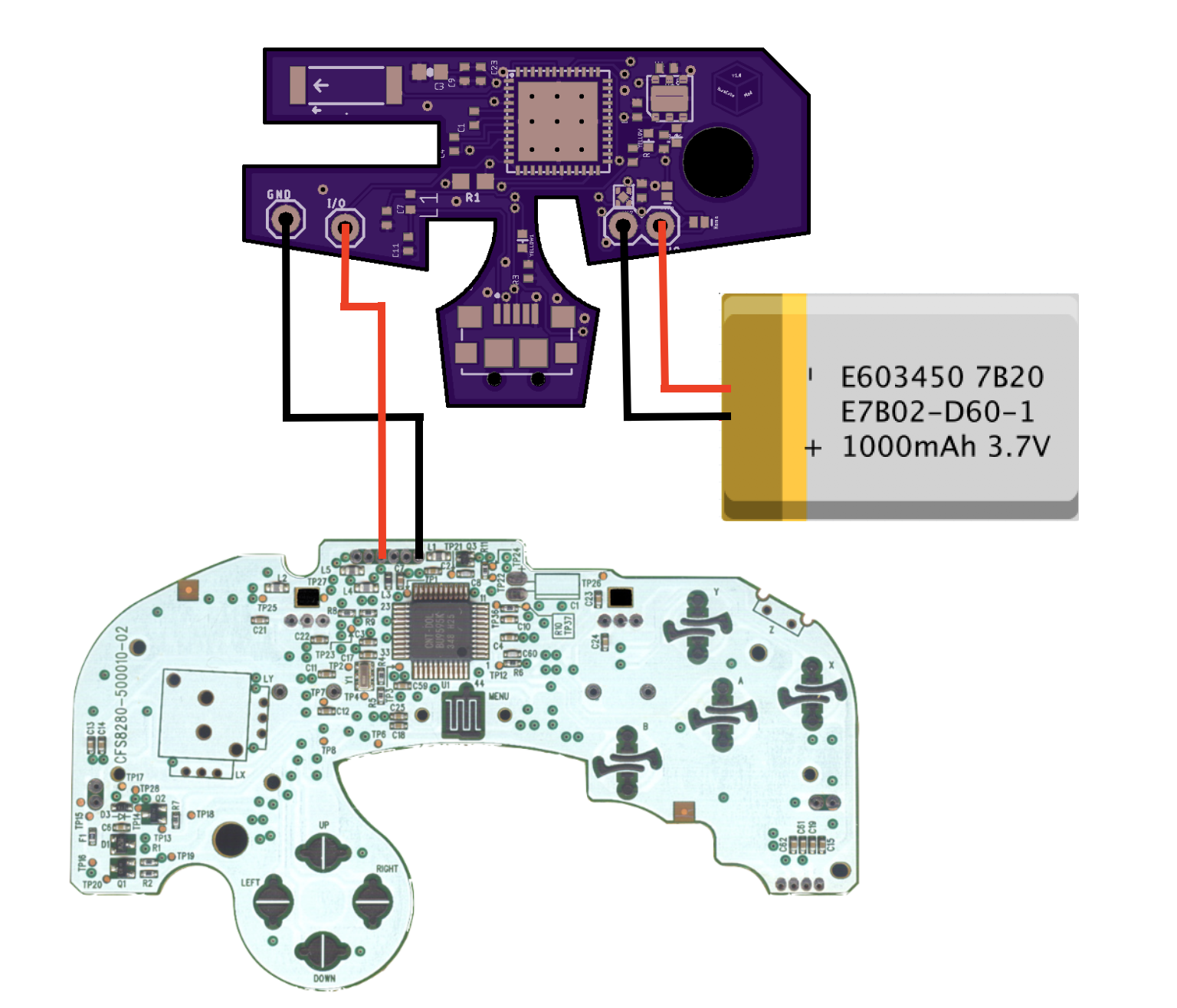
Wiring Up 3ds Sticks To Your Controller Bitbuilt Giving Life

Wiring Diagram Slot Cars Slot Car Racing Slot Racing

How The Sega Dreamcast Was Ahead Of Its Time And Still Failed

This should be clear enough for anyone to understand.
Gamecube controller wiring diagram right stick. When i tried it with a third part controller madcatz microcon it didn t work but i think it s probably just a bit of tweaking of the electronics and. I am in no way associated with sony microsoft or nintendo nor do i claim anything created designed or manufactured by them as my own. Departing from the 3 pronged design of its predecessor the nintendo 64 controller the gamecube controller features two grips with a joystick and directional pad on the left side a small start button in the center and the a b x and y buttons along with a c stick on the right side. C stick and left right shoulder button values from the original official nintendo wired controller dol 003 it says on the bottom of my controller.
Use the flowchart in the pictures above to help diagnose your problem. The controller was stripped of its connector and this wiki shows the subsequent steps to wire the controller to the mbed and code needed to read data through a. Nintendo gamecube controller protocol. When wiring a pcb extracted from a pad controller you need to solder a wire to the signal for each of the needed buttons and one or more wire to each of the unique grounds used by those signals.
It allows you to use two pins to get 6 buttons a d pad up down left right two variable triggers and two joysticks. Note that the gamcube joystick has 6 pins on it. Here s the wiring diagram for the joystick. Video games are awesome buying a 40 50 controller every time something small breaks is not.
I usually only break the control stick so i can make one working controller out of two broken ones if there is no other way to repair them. Double check wiring cross referening the diagram and sodler the jumper cables to the appropriate pins on the cupcade pcb. This instructable will show you how to fix various problems with your remote. The ground is usually shared around in the pcb and therefore can be shared among all the signals.
Note that this is on the back of the board and 1 4 is from right to left on the from of the board. Or has a link to a wiring diagram to replace the n64 analog stick with an if it s a first party n64 controller you can t just rewire a gc stick right. Wiring diagram of analog ptz camera to the dvr the following wiring diagram shows that how to connect an analog ptz camera to the dvr and joystick ptz controller. The end result is hopefully an analog stick with a more traditional feel.
Vc maps the gamecube controller values to certain in game values. I have a few old n64 controllers lying around and figured that it would the circuit i created for reading out the controller is shown in the schematic below. The algorithm poorly recreates the feel of the n64 version of oot. This ess adapter interprets controller input and scales maps it to compensate for the vc map.

Submersible Pump Control Box Wiring Diagram For 3 Wire Single

220v 30a Wiring Diagram Help Page 2 Home Brew Forums Home

Diagram Of A Brake Controller Intallation Tekonsha Diagram

Image Result For Wiring Diagram For Taotao 110cc Atv Motorcycle

Super Nintendo Original Snes Controller Frayed Cord As Is For
Custom Modded Controllers For Xbox One Xbox One Elite Ps4 And

Tingdong For Ps4 Controller Conductive Movie Flex Cable Top
Bluecubemod Bluetooth Gamecube Controller Mod Kit Hackaday Io

Joy Con L R Gray Oem Nintendo Switch Game Controller First

Quadcopter Wiring Diagram Guide Rcdronegood Com Drone Design

Pin On Cool Stuff

Msi Force Gc20 Gaming Controller Cable Usb Pc Smartphone

Single Phase Submersible Pump Starter Wiring Diagram On Water
