Oildyne Trim Pump Wiring Diagram

Oildyne Trim Pump Wiring Diagram H1 Wiring Diagram

Oildyne Trim Pump Wiring Diagram All Wiring Diagrams
Mercruiser Trim System Wiring Diagram H1 Wiring Diagram

Mercury Trim Switch Wiring Diagram Wiring Diagram Source

Sr 8849 Trim Wiring Diagram View Diagram Mercruiser Trim Pump

Gl 8918 Mercruiser Trim Pump Wiring Diagram Schematic Wiring

Bilge pump wiring diagram cmc tilt and trim wiring diagram quicksilver shifter parts diagram mercury outboard trim gauge wiring diagram trim.
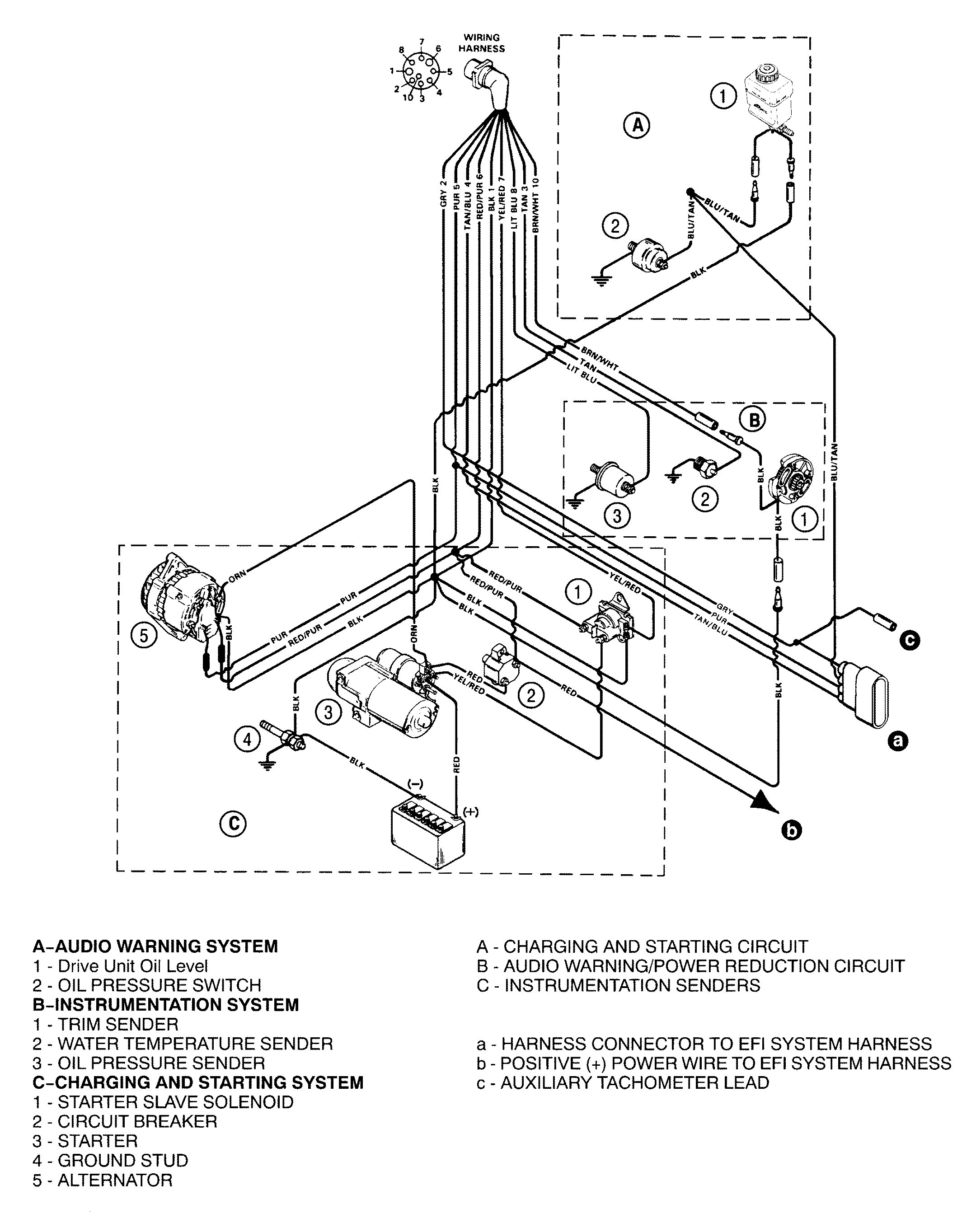
Oildyne trim pump wiring diagram. How to test your tilt and trim pump. It is imperative that personnel involved in the installation service and operation of these parker oildyne units be familiar with how the equipment is to be used. 5a 0 oildyne power trim pump. 6 bravo trim system components.
Mercruiser tilt and trim problems. The blue green wires bring 12 volts from the toggle trim tilt and trailer switches to the two solenoids on the pump assy. Understood prior to installing and operating parker oildyne 108 118 series and 165 175 series hydraulic power units. This mercruiser power trim and tilt system is or oildyne hydraulic pump the trim cylinders a reverse lock valve.
The 108 series models are designed for intermittent service and come in four standard pump sizes which. High pressure pump system this mercruiser power trim and tilt system is electro hydraulically operated. Its electrical sub system consists of a power trim control panel or handle a pump motor and a trim limit switch with connecting wiring. I need the wiring diagram for a mercruiser pre alpha tilt trim lift pump i am not sure it is wired correctly.
July 8th pm. Tained with an ac or dc motor gear pump reservoir internal valving load hold checks and relief valves. Figure 1 shows a typical system. The green wire goes to the down solenoid while the blue wire goes to the up solenoid.
To the toggle up down and trailer up switches. The oildyne division s compact 108 165 series power units let you put the power where you need it. 2 solenoid 2 switch oildyne pump wiring diagram. They should be aware.
6 days ago sae j marine trim pump wiring diagram bennett trim pump wiring diagram mercury trim pump wiring diagram oildyne trim pump. Some models may also be equipped with a trim indicator sender. The trim tilt switches have been messed up in my boat for a long time. Ha and hd dual voltage 1 3 hp 60 50 hz.
Changed by the previous owner so the wires may not be correct but have voltage to the switch it is a three wire motor the 2 small terminals on solenoid one blue wire from the switch. The red wire in the plug sends 12 volts from the pump assy. 6 trim system wiring diagrams. Mercruiser tilt and trim repair.
They re completely self contained with an ac or dc motor gear pump reservoir internal valving load hold checks and relief valves.

Genuine Mercury Mercruiser Parts New Oildyne Trim Pump Assembly
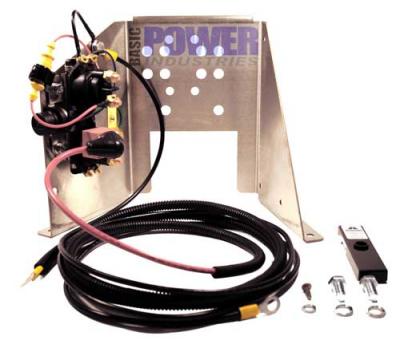
Bracket Trim Pump Stainless Steel Mercruiser Oildyne Prewired