Pcbfm131 Time Delay Relay Wiring Diagram

F delay timer wiring diagram best qd 253 post purge timer f.
Pcbfm131 time delay relay wiring diagram. F delay timer wiring diagram best qd 253 post purge timer f. Terms and conditions about us help site map express methods of delivery via ups and fedex are not guaranteed due to covid 19. It reveals the elements of the circuit as simplified shapes as well as the power and also signal links between the gadgets. If you want to start the device after a certain time by pressing the button you will use the on delay timer.
F delay timer wiring diagram best qd 253 post purge timer f. Adjusting the delay time is often as simple as turning a knob. Click here for more information on ups. Please look at this picture.
The time relay is divided into the on delay timer and the off delay timer. At the end of the time delay t1 the output is energized. Application requirements for time delay relays tdrs david bredhold. To control a load a lamp or a pump we should connect the wire to normally open contact.
When the trigger is removed the output remains energized for the time delay t2. Make sure to remove s5 jumper. If the trigger is removed during time delay. Assortment of time delay relay wiring diagram.
The basics of time delay relays. Goodman b1370751 0130m00025 relay. Fan blower control replacement for goodman b1370735s pcbfm131s control boards. Goodman b1370738 eep time delay relay.
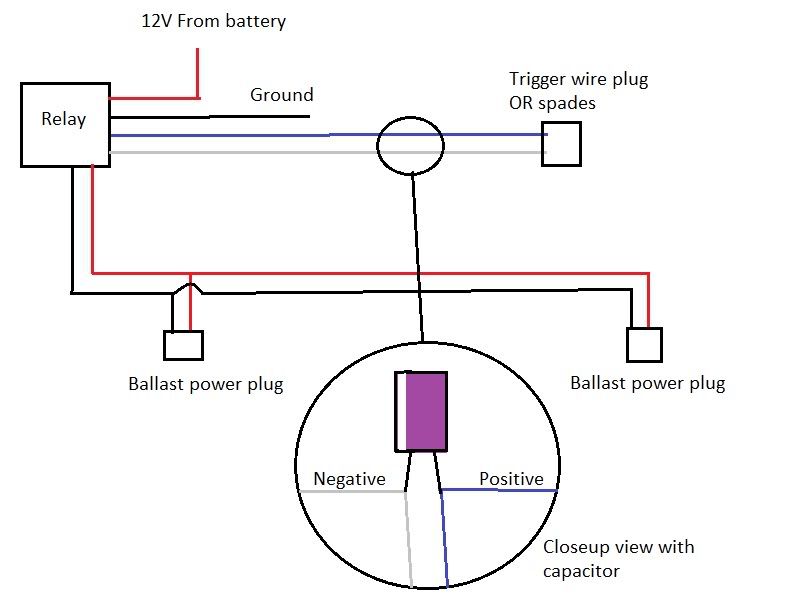
A wiring diagram is a streamlined conventional photographic depiction of an electric circuit. No matter what the application is when a definite purpose solution is required time delay relays tdrs can provide simple reliable and economical control. Goodman pcbfm103s time delay relay board. Applied the time delay t1 begins.
Board electronic blower time delay relay 151 pcbfm131 wire assy 9 pin female connector m1 m2 m3 m4 171 0259a00001p wire assy 9 pin female connector m5 m6 m7 m8 m9 m10 m11 m12 m13 m14 m15 m16 m17 m18 m19 m20 m21 171 0259a00005p 181 0259a00002p wire assy 9 pin male connector 201 0154a00000bl drain pan gasket qty 2. Delay on break timer wiring diagram gallery fancy time delay relay wiring diagram image electrical circuit. At the end of the time delay t2 the output is de energized and the time delay relay is ready to accept another trigger.


