Vdo Gauge Wiring Diagram Schematic

12 Autometer Electric Speedometer Wiring Diagram Wiring Diagram

Pin Di Engines

Pin On Car Diagram

16 Basic Electric Drill Wiring Diagram Wiring Diagram In 2020

Vdo Gauge Wiring Diagram Schematic H1 Wiring Diagram
9b1 Vdo Fuel Gauge Wiring Diagram Wiring Library
Assembly or wiring instructions.
Vdo gauge wiring diagram schematic. If you have additional questions please contact vdo. Always disconnect the battery ground before making any electrical connections. 158 or equivalent 1 4. Aftermarket technical support troubleshooting.
Installation instructions 1 caution. Lamp socket push in wedge type 2 3. Lamp socket push in wedge type 1 3. 161 or equivalent 2 4.
Ocean link display 4 inches wiring schematic 2018 ocean link display 7 inches owners manual multilanguage 2018. Temperature pressure or fuel gauge 2 66 mm diameter 1 2. Junction and attach the wire from the speedometer. Siemens vdo pitot pressure to speed pulse system 2004.
The final ground run using 14 gauge wire should be connected to a good. Vdo spin lok clamp or mounting bracket 1 5. Vdo gauges wiring diagrams and boat tach diagram e z go golf cart for boat gauge wiring diagram for tachometer image size x px and to view image details please click the image. Ocean line freshwater level gauge 2003 viewline 52mm wiring diagram 2014 viewline level gauges 52mm 2008.
Light bulb 12 volt g e. Repair service for oem instrument clusters and systems merri mcintyre phone. The ground œ wire is also run in series including the light socket ground. Finally connect the red wire from the tachometer to the red wire in the shielded cable.
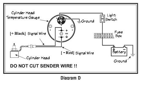
Here is a picture gallery about boat gauge wiring diagram for tachometer complete with the description of the image please find the image you need. Light bulb 12 volt g e. The remaining white tachomter wire is for illumination and is connected as tach tach posi lock connector signal diagram i wiring to msd 7al ignition page 5 you must use two sets of shielded wire for this installation. Refer to diagram d for the proper wiring of the speedometer.
Diagram a vdo tachometer with hourmeter is programmable from 5 to 200 pulses per revolution vdo vdo item description quantity 1. Read these instructions thoroughly before making installation. Repair service for aftermarket gauges and accessories connie heflin phone. 0 electronic speedometer hall effect sender installation instructions and wiring diagram 7udqvplvvlrq type a speedometer 4 wire system 5 7.
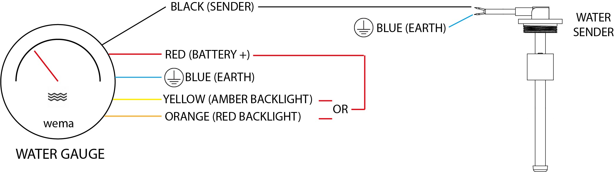
Heritage chrome f water temperature gauge use with vdo sender viewline sterling f c water temperature gauge 12v with sender kit. Only connect cables according to the electrical wiring diagram. Wire gauges in series from a positive accessory to a source which is not already overloaded with fans air conditioning and such. Vdo wiring diagrams diagram will open in a new window.

004a 333241 Vdo Synchronizer Wiring Diagram Wiring Library

Wm 0521 Receiver Circuit Diagram On Vdo Oil Pressure Gauge Wiring

Awesome Wiring Diagram Potentiometer Diagrams Digramssample

Internal Chip Function Diagram For Bmw Msd80 2 Dme

How To Wire Dual Electric Cooling Fans Electric Cooling Fan

120 Volt Schematic Wiring Diagram All Wiring Diagrams
Auto Meter Volt Gauge Wiring Diagram All Wiring Diagrams

Pin On Baja Bugs

19 Stunning Free Auto Wiring Diagrams For You Ballast Led Tubes

Pin On Motors Parts Accessories

Pin On Engine Wiring And Tuning

Garmin Fuel Wiring Diagram Free Picture Schematic Wiring Diagram

Vwvortex Com Here S A List Of Fuses For Mkiv Cars Fuse Too For
